
Getting Started Moldmaking with a hand placed mold designed for use in a Morgan injection molding machine.
Injection moldmaking can be a practical way to learn machining because one small project brings together layout, milling, drilling, turning, fitting, measuring, plastics, and problem solving. This introduction is intended to help a beginner understand the process before attempting a more advanced mold.
Start with the Whole System
A successful molded part is not designed separately from its material or its mold. The part, the plastic, the mold geometry, and the molding process all affect one another. A beginner should get used to thinking about the complete system before cutting metal.
Preparation
Begin with the job the finished part must perform. Decide whether it needs to be rigid or flexible, tough or merely decorative, dimensionally accurate, resistant to impact, or able to flex repeatedly. Those requirements help determine which plastic is suitable, and the plastic then affects the shape and dimensions of both the part and the mold.
For a first project, it is useful to compare a small group of relatively low-temperature thermoplastics rather than trying to learn every resin at once. Exact properties vary with grade, so the manufacturer's data sheet for the actual resin should always be checked before final dimensions and molding conditions are chosen.
| Plastic | General mechanical character | Shrinkage tendency | Typical melt / processing temperature | Part-design notes | Molding / mold-design notes |
|---|---|---|---|---|---|
| GPPS General-purpose polystyrene |
Hard and rigid, but comparatively brittle. | Low | 190–240°C | Good for simple, dimensionally stable shapes. Avoid thin projections and sharp inside corners where impact is expected. | Relatively easy to mold and useful for learning dimensional accuracy because shrinkage is modest. |
| HIPS High-impact polystyrene |
Rigid, but tougher and less brittle than GPPS. | Low | Check the exact grade TDS | A good choice for simple utility parts that need more impact resistance than GPPS. | Generally retains the forgiving moldability of the polystyrene family. |
| PP Polypropylene |
Tough, light, and somewhat flexible; stiffness varies greatly by grade. | Medium to high | 200–250°C | Well suited to useful knobs and handles. Uniform wall thickness and smooth transitions help control warpage. | More shrinkage than PS. Gate placement, packing, cooling, and even wall thickness become more important. |
| HDPE High-density polyethylene |
Tough, moderately stiff, and resistant to many chemicals. | High | 190–230°C | Useful for durable utility parts. Allow for greater dimensional change as the part cools. | A good material for teaching shrink allowance and the effects of uneven cooling. |
| LDPE Low-density polyethylene |
Soft, flexible, and difficult to fracture. | High | 170–210°C | Useful when flexibility is desired, but not ideal where a very stiff machine-control knob is required. | Shows how two plastics from the same broad family can require different design expectations. |
| ABS | Rigid with good impact resistance and a solid, tough feel. | Low | 220–260°C | Useful for housings, handles, and durable parts where strength and dimensional stability both matter. | Generally molds with relatively low shrinkage, making it friendly for dimensional work. |
| Hytrel® | Flexible to semi-rigid, very tough, resilient, and resistant to repeated flexing. | Grade-dependent | Melting point 210–220°C; check the exact grade for processing temperature | Useful for resilient grips, bumpers, flexible parts, and parts that must bend repeatedly. | Better treated as a next-step material because processing behavior depends strongly on grade and preparation. |
The temperature values above are generalized comparison values, not settings for every resin sold under that plastic name. Different grades can require different conditions. For an actual mold, always use the technical data sheet for the exact resin grade being molded.
Those additional properties become more important as a design becomes more serious. Melt Flow Index helps describe how readily a resin flows under specified test conditions; tensile strength relates to how much pulling stress the material can withstand; flexural modulus is a useful indication of stiffness; and density affects part weight and the amount of material required.
Material Preparation Matters Too
Plastic pellets can pick up moisture while exposed to the air. How much this matters depends strongly on the resin. Some materials absorb very little moisture, while others are much more sensitive and may require drying even when the pellets look perfectly dry. Moisture can cause streaks, bubbles, splay, poor surface finish, or loss of properties in the molded part. Always check the drying instructions for the exact resin grade being used.
A freshly opened, properly sealed bag may sometimes be ready to use, particularly for materials that do not normally require aggressive drying, but do not assume that every new bag is dry enough. Material that has been open in the shop should be treated with more suspicion. Batch drying can be done in shallow trays in a suitable temperature-controlled drying oven, while a hopper dryer can dry and warm the pellets as they are fed to the machine. Preheated dry material can reduce the heating load on the machine and can improve recovery time and cycle consistency.
Keep Wall Thickness as Uniform as Practical
Uniform wall thickness is one of the most useful early design rules. A thick section contains more hot plastic than a thin section, takes longer to cool, and usually shrinks more. If a section is unnecessarily heavy, the outside can become solid while the center is still cooling and contracting. The result may be an inward depression, or sink mark, on the surface.
Whenever possible, use smooth transitions instead of sudden changes from thick to thin, add generous radii rather than sharp corners, avoid unnecessary solid masses, and give the part enough draft that it can be removed from the mold. These decisions are part of designing the product, not corrections to be added after the mold is finished.
Tools and Equipment
Start with the Morgan G-100T machine limits

In this course we are using the Morgan G-100T as our example molding machine. Before designing a mold for any shop, first check the molding machine or machines actually available there and collect the same kinds of information: mold-size limits, closed mold height, clamp force, injection pressure, shot size, nozzle geometry, mounting provisions, ejector locations, and available opening travel. The mold must fit the machine as well as the part.
For our example, the important Morgan G-100T limits and machine features are summarized below. These are the values we will use as we develop the beginner mold.
| Machine feature | Morgan G-100T information useful to the mold maker |
|---|---|
| Maximum mold plan area | 8 × 11 inches. |
| Closed mold height | 5 inches minimum; 7-1/2 inches maximum. Do not confuse this adjustment range with mold-opening travel. |
| Maximum clamp force | 20 tons. |
| Maximum injection pressure | 12,000 PSI. |
| Maximum shot size | 4 ounces (approximately 6 to 7.5 cubic inches, depending on the material). |
| Lower-platen clamping holes | Eight 3/8-16 tapped holes, equally spaced on an 8-inch diameter bolt circle, with the pattern rotated 22-1/2 degrees from the machine X/Y axes. If machine center is treated as X0,Y0, the eight centers are the permutations of approximately ±3.6955 and ±1.5307 inches. |
| Knock-out / ejector clearance holes | Four 11/16-inch diameter clearance holes on a centered 4 × 2 inch rectangular pattern. With machine center as X0,Y0, the nominal centers are X = ±2.000, Y = ±1.000 inches. Morgan uses 3/8-16 threaded knock-out rods. |
| Table center locator | 3/8-inch diameter locating stud at machine center. |
| Upper-platen mold attachment | Four shoulder-bolt locations are best established from the actual upper platen. Morgan's setup procedure uses a 3/8-inch transfer punch through the upper-platen holes to mark the mold. The mold is then removed and drilled/tapped; the usual arrangement is a 3/8-inch shoulder bolt with a 5/16-18 threaded end. |
| Ball-nose nozzle | Morgan's standard ball nozzle has a 1/2-inch spherical radius. Standard orifice sizes are 1/8 inch (A), 3/16 inch (B), and 1/4 inch (C). The mold sprue entrance should match the nozzle being used, or be only slightly larger. |
| Mold-opening / platen travel | Verify on the actual machine before designing automatic ejection or other mechanisms that depend on opening stroke. The 5 to 7-1/2 inch mold-height range is not the same thing as platen travel and should not be used as a substitute for that measurement. |
These dimensions establish the machine envelope and mounting interface; they do not force every mold to use every machine feature. A simple hand-placed mold may use none of the knock-out or upper-platen mounting provisions. When those features are used, work from the actual machine and verify critical locations before drilling the mold. Morgan-Press Operating Instructions.
Plastic material drying
Plastics dryer
A plastics dryer belongs with the molding equipment rather than the machine-shop tools. Many molding resins must be kept dry before processing, and some grades require controlled drying to prevent moisture-related defects in the finished part.
A hopper dryer is especially convenient because the material can be dried and kept warm at the molding machine, then fed directly into the machine hopper. The required drying temperature and time depend on the exact resin grade, so the material manufacturer's drying instructions should be followed.
Machine-shop tools and equipment
A first Morgan mold does not require a large toolroom, but it does require basic metalworking equipment and accurate measuring tools. We will begin with the measuring tools, because nearly every operation that follows depends upon knowing what size the work actually is.
If any of these machines are new to you, open the first-use fundamentals included below and practice on scrap material before beginning the mold. The later moldmaking steps assume that the operator already understands the basic controls, workholding, measuring, and safe use of the machine being used.
Measuring tools
Dial or electronic caliper
A dial or electronic caliper with a measuring range of at least 6 inches is a basic requirement for this project. It should have a resolution of 0.001 inch so small changes in the size of the mold blocks and machined features can be followed as the work approaches its finished dimensions.
A typical caliper of this type can measure outside dimensions, inside dimensions, step dimensions, and depth. That makes it useful throughout the moldmaking process for checking plate length and width, thickness, hole or recess sizes, shoulders, and many other features.
Cutting stock
Band saw
A metal-cutting band saw is the preferred tool for preparing the aluminum stock for this project. The saw must have enough capacity to accommodate the width and thickness of the aluminum plate or block being purchased. The stock is normally cut slightly oversize so the milling machine can later square the faces and bring the block accurately to its finished dimensions.
The band saw is also useful for cutting guide-pin stock, rods, spacers, and other small pieces to rough length before they are finished on the lathe or milling machine. Use a blade and cutting speed appropriate for aluminum and the section being cut.
Milling machine and accessories
The milling machine is the principal machine tool used to square the mold blocks, locate and drill holes accurately, machine the cavity, cut slots, and produce many of the other features in the mold. Size and working capacity are very important. The table must have enough X- and Y-axis travel to traverse the mold blocks being used, with additional room for clamps and workholding.
Vertical clearance is just as important as table travel. A mold block may be mounted in a vise or on a rotary table, and the spindle must still have enough room above the work for the collet or tool holder, drill, reamer, end mill, ball-end mill, or other cutter being used. A machine that appears large enough for the bare mold block can become too small once the workholding and cutting tool are included.
A machine with a head that can tilt and swivel is especially useful. These adjustments make angled drilling and milling possible and give the mold maker more ways to approach a difficult feature without elaborate fixtures.
Useful milling-machine accessories for this project include:
- A sturdy milling-machine vise large enough for the mold blocks
- A clamp kit for holding work directly to the table
- Parallels and suitable support blocks
- A rotary table for circular or radial features
- Collets or other suitable tool holders
- End mills and ball-end mills appropriate for aluminum
- Drills and reamers in the sizes required by the drawing
Using a manual milling machine: first-use fundamentals
Before machining an actual mold block, a first-time operator should practice the basic motions and setup procedures on scrap material. This overview explains the ideas used later in the moldmaking steps, but the instructions for the particular milling machine and the shop instructor's safety procedures always take precedence.
Know the machine axes and controls
On a conventional vertical mill, the long table travel is normally called the X axis and the in-and-out cross travel the Y axis. Vertical movement is the Z axis. A knee mill can change Z by moving the table with the knee, while the quill provides a shorter independent vertical movement of the spindle for drilling, boring, and limited plunging. Before making a cut, know which control is moving the work and which is moving the cutter.
Understand and measure backlash
Lead screws and nuts normally have some clearance. When a handwheel is reversed, the wheel may turn before the table begins moving in the new direction. That lost motion is backlash. There is no universal backlash value and no universal number of turns needed to remove it; the actual machine must be checked. For accurate positioning, approach the final coordinate from a consistent direction. If the target is overshot, back away farther than the known backlash and approach the coordinate again from the original direction.
Set the vise and seat the work
Keep the table, vise base, jaws, parallels, and workpiece free of chips and burrs. When the operation requires the vise to follow the machine's X travel, indicate the fixed jaw and adjust the vise until its alignment is suitable for the accuracy required. Do not chase a displayed 0.000 reading as though it were a universal requirement; understand the indicator variation and decide whether it is acceptable for the job.
Parallels can raise a block above the vise jaws and provide a repeatable supporting surface. Tighten the vise, then seat the work gently with an appropriate non-marring or dead-blow mallet while confirming that both parallels remain trapped evenly. A chip under the work or a block resting on only one parallel can introduce more error than a careful handwheel setting can correct.
Conventional and climb milling
In conventional milling, cutter rotation at the point of contact opposes the direction of table feed. In climb milling, cutter rotation tends to pull the work in the same direction as the feed. On a manual machine with noticeable backlash, climb milling can pull the table into that clearance and make the cut unexpectedly aggressive. For a beginning operator on a conventional manual mill, conventional milling is therefore the safer default for side-cutting until backlash, cutter forces, and the condition of the machine are understood. Climb milling is not forbidden in all manual work, but it should be used only when the machine, setup, and operator are suitable for it.
Spindle speed and feed rate
Cutter speed depends on the work material, cutter material and coating, cutter diameter, machine rigidity, lubrication, and the operation being performed. Use the cutter manufacturer's recommendations whenever they are available. A useful inch-unit relationship is:
RPM ≈ (SFM × 3.82) ÷ cutter diameter in inches
The traditional quick shop estimate uses 4 instead of 3.82.
A calculated feed rate can then be estimated from RPM × number of cutting edges × chip load per tooth. On a hand-fed machine, that calculation is guidance rather than a promise that the operator can or should crank at one exact rate. Feed smoothly enough that the cutter is making chips rather than rubbing, while watching and listening for chatter, overload, chip packing, or an unsafe change in cutting force.
Touching off and establishing zero
A surface zero can be established with an edge finder, indicator, touch-off device, or a thin measured paper feeler. For a beginner using paper, the safest procedure is to use the method approved by the shop and keep fingers clear of the cutter. With the spindle stopped, a flute can be rotated by hand while the cutter is brought down until it just drags a known-thickness paper feeler; the paper thickness is then accounted for when setting the reference. The purpose is to establish a repeatable datum, not to tear the paper with a running cutter.
A useful first practice cut
- Clamp a small scrap block of aluminum securely on clean parallels in an aligned vise.
- Install a sharp end mill suitable for aluminum and make certain the tool is held securely.
- Select a conservative spindle speed from reliable tooling data for that cutter and material.
- Establish a surface reference, move the cutter clear of the work, and set a shallow practice cut.
- Lock or secure unused machine motions as appropriate for the particular mill.
- Make a steady conventional pass completely clear of the work before changing direction.
- Stop the spindle before measuring, clearing chips by hand, or deburring the practice piece.
- Measure the result and compare the actual cut with the handwheel or DRO movement that was commanded.
The practice cut should teach control, not test the maximum capability of the machine. Depth of cut, cutter engagement, spindle speed, and feed should all remain conservative until the operator understands how that particular mill responds.
Lathe and turned mold parts
A metalworking lathe should be considered the proper machine for making guide pins, sleeves, bushings, inserts, spacers, and other turned mold components. Most of these parts are comparatively short, so a lathe with roughly 24 or 36 inches between centers is generally satisfactory for the type of mold work described in this course.
For moldmaking, swing over the bed can be more important than having an especially long bed. A machine with greater clearance between the bed and spindle centerline, or a removable gap bed, may allow an entire mold block or plate to be mounted for turning a circular cavity or other large round feature directly in the mold. This can greatly expand what can be done without special boring or rotary-table setups.
Using a manual lathe: first-use fundamentals
A lathe reverses the relationship seen on the milling machine: the workpiece rotates while a cutting tool is fed against it. Before turning guide pins, sleeves, bushings, or inserts for a mold, a beginner should first practice facing and simple outside-diameter turning on scrap stock under qualified supervision.
Chuck-key and rotating-work safety
Remove the chuck key immediately after tightening or loosening the chuck. A useful habit is to keep a hand on the key whenever it is in the chuck and never leave it inserted while reaching for another tool. Tie back long hair, secure loose clothing, remove jewelry that could be caught, wear suitable eye protection, and do not wear gloves near rotating work. Keep hands away from chips and rotating stock; stop the spindle before measuring or clearing entangled chips.
Know the controls
The carriage moves the cutting tool parallel to the spindle axis, normally called the lathe's Z axis. The cross-slide moves the tool toward or away from the spindle centerline and is normally the X axis. The compound rest can be swiveled to an angle and used for short tapers, controlled small movements, and some threading operations. Before starting the spindle, make certain the intended tool path will clear the chuck, jaws, tailstock, and tool post.
Set the cutting tool on center
Tool height strongly affects cutting action and surface finish. One practical setup method is to bring a tailstock center near the cutting tool and adjust the tool tip until it visually matches the center point, then lock the tool post securely. The tool need not be described as mathematically perfect to begin a practice cut, but it should be very close to spindle center and should cut cleanly without obvious rubbing, digging, or leaving an unexplained center nub during facing.
Hold the work rigidly
Unsupported work should project from the chuck only as far as the operation requires. There is no single safe stick-out ratio that applies to every diameter, material, chuck, speed, or cut. Long or slender work may require support from the tailstock, a steady rest, or another appropriate method. For the short guide pins and inserts used in this beginner mold, short, rigid setups are generally preferred.
Calculate a reasonable spindle speed
On a lathe, surface speed depends on the diameter of the rotating work. Use the cutting-tool manufacturer's surface-speed recommendation when available. A useful inch-unit relationship is:
RPM ≈ (SFM × 3.82) ÷ work diameter in inches
The traditional quick shop estimate substitutes 4 for 3.82.
For example, a 1-inch diameter aluminum bar at a conservative 250 SFM works out to about 955 RPM, or approximately 1,000 RPM using the quick ×4 shop formula. That is an example calculation, not a universal setting. Tool material and geometry, the alloy, lubrication, rigidity, and the operation may justify a substantially different speed.
A first facing cut
- Clamp a short piece of round scrap stock securely in the chuck and remove the chuck key immediately.
- Set a sharp facing/turning tool close to spindle center and confirm clearance from the chuck jaws.
- Select a conservative spindle speed appropriate for the stock diameter and cutting tool.
- Bring the tool close to the rough end and establish a light face reference.
- Move the tool clear, advance only a shallow amount into the end face, and make the facing pass.
- Feed the cross-slide smoothly from the outside diameter toward the center without dwelling in one spot.
- Retract the tool clear, stop the spindle, deburr if needed, and measure the result.
Working specifically with 7075-T6 aluminum
The mold blocks in this course are based on 7075-T6/T651 aluminum. Compared with 6061-T6, 7075-T6 is generally harder and stronger, so machine rigidity, short tool overhang, sharp cutting edges, secure workholding, and control of chatter become especially important. Use tooling intended for aluminum and keep chips from packing or welding to the cutting edge. A suitable aluminum cutting fluid can help, provided it is compatible with the machine, the tool, and the shop's safety practices.
Published speed, feed, nose-radius, and depth-of-cut tables should be treated as starting references, not absolute rules. HSS and polished carbide can both machine 7075 successfully, but their useful speed ranges are quite different. Use current tooling data for the actual cutter or insert whenever possible, then begin conservatively on a small machine and adjust according to chip formation, finish, cutting force, temperature, and chatter. Avoid repeated light rubbing that merely polishes the surface instead of producing a proper chip.
Chip shape depends strongly on tool geometry, feed, and depth of cut. Do not assume 7075 will always form short chips; long or sharp chips must still be treated as an entanglement and cut hazard.
Files, sanding, and polishing
Hand finishing is not merely cosmetic. Files and abrasives can remove burrs, establish or refine a surface, blend machining marks, and prepare a cavity for easier part release. The important lesson is to improve the surface without destroying the geometry already machined into it. A shiny surface that has become rounded, tapered, or undersize is not an improvement.
Using files, sandpaper, and polishing compounds
Start with a stable working position
Clamp the work securely at a comfortable height that allows the file to remain flat through the stroke. Work near elbow height is a useful starting point for many people, but it is an ergonomic guideline rather than an exact dimension. Stand so the stroke can be driven smoothly by the arms and body without rocking the file over the edges of the work.
Cross-filing establishes and corrects the surface
For broad flat work, file diagonally across the surface, often around 45 degrees to its long axis, then change direction for the next series of strokes. The crossing scratch patterns make it easier to see where the file is cutting and where old low spots remain. Keep the file supported over as much of the work as practical and avoid tipping it as the stroke enters or leaves an edge.
Draw-filing refines file marks
Once the surface is close to size and flatness, a smooth file can be used in a draw-filing motion. Hold the file with both hands and move it sideways across the work while keeping it flat. The lighter scraping action can reduce the ridges left by ordinary cross-filing and prepare the surface for abrasive paper.
Prevent file pinning
Small chips can become trapped in file teeth and score the work. Clean the file frequently with a proper file card or brush suited to the tooth pattern. Chalk is also commonly rubbed into file teeth to help reduce loading and pinning, especially on softer metals such as aluminum. If a deep scratch suddenly appears, stop and clean the file rather than continuing to drag the trapped particle across the work.
Sand on a firm backing surface
Sandpaper wrapped around a hard, flat block helps preserve flatness and sharp edges. Fingers alone conform to hollows and edges and can quickly round a carefully machined corner. Begin with a grit fine enough to remove the existing file or machining marks without taking unnecessary material. A practical example might begin around 220 or 320 grit, followed by 400, 600, 800, and 1200 where a progressively finer finish is wanted. Those numbers are an example sequence, not a mandatory recipe.
Changing the sanding direction about 90 degrees between grits makes the previous scratch pattern easier to see. Do not move to the next finer abrasive until the scratches from the previous step have been removed. On aluminum, use an abrasive and lubricant appropriate for aluminum and keep the paper clear of loaded metal particles. Excessive pressure can create deeper scratches and distort edges.
Polishing comes after the geometry is correct
Polishing compounds remove much smaller scratches than files or coarse paper. For broad flat surfaces, use a firm backing block or controlled polishing support rather than a soft pad that can roll over edges. Clean the work thoroughly whenever changing to a finer abrasive or compound so coarse particles are not carried into the next step. Choose the polishing compound for the actual metal and desired finish; steel and aluminum do not necessarily use the same system.
A reflective finish is not the same thing as measured flatness, and it is not automatically equivalent to a specified mold-finish grade. On the mold's parting surfaces, preserving flatness and sealing contact is more important than achieving a mirror appearance. On a cavity surface, polish in a manner that supports part release and does not erase intentional draft, radii, dimensions, or texture.
| Stage | Typical tool | Main purpose |
|---|---|---|
| Geometry | Flat or mill file | Remove burrs/high spots and bring the surface toward shape and size. |
| Refinement | Smooth file / draw-file | Reduce coarse file marks while preserving flatness. |
| Coarse sanding | 220–600 grit on a hard block | Replace file marks with a controlled abrasive scratch pattern. |
| Fine sanding | 800–1200 grit or finer as needed | Prepare for a fine functional or cosmetic finish. |
| Polishing | Compatible fine compound on controlled backing | Reduce very fine scratches without rounding geometry. |
Stop and measure often when hand finishing a dimensioned mold component. Every abrasive step removes metal, even when the change is difficult to see.
Other basic shop equipment
- Layout dye, rule, square, and scriber
- Allen wrenches and ordinary hand tools
- Eye protection and other required shop PPE
Not every shop will use the same tools or sequence. The objective is to understand the operation being performed and use the machine and workholding method appropriate to the equipment available.
Our First Part Design
A beginner mold should be deliberately simple. One useful approach is a small knob or handle whose complete cavity is machined into only one mold half. The mating half can remain largely flat. This avoids the difficult job of machining two matching cavity halves and makes it easier to see how the mold works.
A bolt, threaded stud, nut, or other metal insert may be held in position while the plastic is molded around it. The finished part then becomes a useful shop knob or handle rather than only a test piece. A direct sprue can feed the cavity without a complicated runner system.
Removing a part from a mold by hand can be difficult. This first part design has both sprue and cavity located in the top half of the mold. The part will naturally tend to stick in that half. However, being molded onto a screw or bolt, it may be pulled out by it. And if by chance the part is stuck in the lower mold half, possibly because the insert (bolt) was forgotten, then it may be removed by pulling on the sprue instead.
What the project teaches
- Reading and working from a drawing
- Measuring and laying out metal stock
- Squaring and facing mold plates
- Drilling, reaming, and fitting holes
- Basic milling of a cavity
- Simple lathe work for round features or inserts
- Understanding sprues, vents, draft, and parting surfaces
- Fitting, mounting, testing, and correcting a mold
Keep the first project simple
- No undercuts
- No cam slides
- No automatic ejector system
- Generous radii and smooth transitions
- Enough draft for easy part removal
- One-sided cavity whenever practical
- A shape that can be inspected and measured easily
Step-by-Step: How a Simple Mold Is Made
-
1. Design a part for molding
Decide first what the finished part must do, then choose a suitable plastic and shape the part around that material's behavior. For a first project, select a simple knob or handle with no undercuts, reasonably uniform wall thickness, generous radii, and enough draft for removal. Decide where the parting surface will be and how the finished part will come out of the cavity. -
2. Draw and dimension the mold
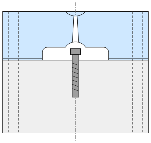
Before cutting aluminum, make three orthographic drawings of the proposed mold: a top view, front view, and side view. Together these views should establish the outside dimensions of the mold and show the cavity, sprue, guide pins, insert location, and any mounting features that must be allowed for.
Basic hand-placed mold: three orthographic views
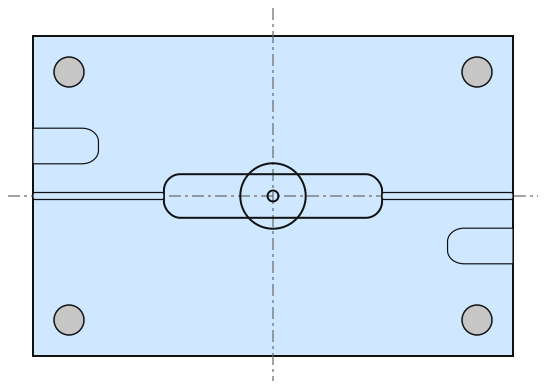
Top view From sketch to working drawing
Mold design often begins as an initial sketch on graph paper rather than as a finished technical drawing. The purpose at this stage is to establish the general size, proportions, and relationship of the mold, part cavity, sprue, guide pins, and other features.
Dimensions, not shown on these sketches, would be added once the initial layout had been determined.
For this example our dimensions would be:
- Overall mold: 5.50 × 4.50 × 5.00 in.
- Upper mold half: 2.00 in. high
- Lower mold half: 3.00 in. high
- T-handle body: 2.50 × 0.50 in.
- Center pocket: 7/8 in. dia. × 3/4 in. deep
- Guide pins: 3/8 in. dia., 4 places
- Guide-pin centers: 9/16 in. from adjacent edges
- Nozzle seat: 1 in. ball-end mill; about 3/4 in. opening
- Sprue: 1/8 in. at the nozzle side, tapered larger toward the cavity
- Captured insert: 1/4-20 socket-head cap screw
Front view 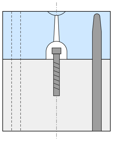
Right-side view Choose the mold material
For these small aluminum molds, Delphi has had good results using 7075-T6. When plate is being purchased specifically for a new mold, 7075-T651 is an especially useful form of the same high-strength alloy because the plate has been stress relieved after heat treatment. That can help reduce movement as substantial amounts of metal are machined away.
Other aluminum should be substituted only when it offers a comparable or better combination of strength, hardness, machinability, and dimensional stability. 7050-T7451 or 7050-T7651 are examples of high-strength plate with good toughness and resistance to stress-corrosion cracking. High-strength 7000-series aluminum mold plate made specifically for injection-mold tooling can also be suitable. For a beginner project, however, 7075-T6/T651 provides a simple and proven starting point.
The alloy and temper are part of the mold design and should be written on the drawing and material list before stock is purchased.
Rule 1: Keep at least 1 inch of metal around the part
For this beginner mold, maintain at least 1 full inch of aluminum between the part cavity and the outside of the mold in every direction, including below the deepest portion of the cavity. This extra material provides strength and a safety margin against cracking or breaking under injection and clamping pressure.
Establish the mold height
The total closed mold stack must fit the Morgan press's 5-inch minimum to 7-1/2-inch maximum mold-height range. For this project, work to at least the 5-inch minimum. A mold that is thinner than this can use a suitable spacer or bolster rather than making every mold plate unnecessarily thick. Do not exceed the 7-1/2-inch maximum closed stack height.
Keep the upper mold half only as thick as needed for strength and the features it carries. The sprue passes through this upper section, so unnecessary thickness makes an unnecessarily long sprue and wastes plastic on every shot.
Allow room for four guide pins
Use four guide pins so the mold halves return to the same position as the mold closes. 3/8-inch diameter guide pins are sufficient for this first mold. Locate each pin center at least 1.5 times the pin diameter from either adjacent mold edge. For a 3/8-inch pin, that minimum centerline distance is 9/16 inch.
The guide-pin locations must not reduce the required 1-inch safety margin around the cavity. If the cavity and its safety zone need more room, increase the mold length or width rather than crowding the guide pins toward the part.
Option: Plan ahead for automatic opening
If the mold may later be used for more than a few sample parts, make the mold large enough to accommodate the upper-platen shoulder bolts used to attach the upper mold half to the moving platen. This allows the press to open the mold automatically instead of requiring the entire mold to be placed and removed by hand for every shot.
Allow room for these mounting locations while laying out the cavity and guide pins, but do not invent their coordinates from a sketch. Morgan's setup procedure locates the four upper-platen attachment holes by placing the mold in the press and using a 3/8-inch transfer punch through the actual upper platen. The mold can then be removed, drilled, and tapped for the shoulder bolts. This automatically references the mold to the machine actually being used.
If the mold will be opened by the press, also provide a means to clamp the lower mold half to the machine's lower platen. This is usually done with a slot across the front and back faces of the mold. The slot must suit the clamp kit, provide a secure grip, and leave enough metal in the clamping ledge for strength.
A similar clamping slot may also be included for holding the block to the milling-machine table. This can eliminate some vise setups and can allow a surface to be machined without moving clamps out of the cutter's path. These slots must still be included in the mold design so they do not interfere with the pins or create a thin, weak area near the part.
Think of the layout as a system: part envelope → 1-inch safety margin → guide-pin space → optional upper-platen mounting space → final mold length and width → required mold stack height.The next step is learning how these three views are related and how drafting uses hidden lines and cutting-plane lines to show features that cannot be seen directly.
Use standard mechanical-drafting conventions
Mold drawings do not use a completely separate drafting language. They are mechanical drawings first, with additional information needed for molding. In U.S. practice, the ASME Y14 family covers subjects such as line conventions, orthographic views, and dimensioning and tolerancing, while ASME Y14.8 adds conventions for cast, forged, and molded parts. International practice uses the ISO 128 series for lines, views, sections, and cuts, with ISO 10135 covering drawing indications for molded parts. A beginner does not need to memorize the standards, but should learn the basic conventions so another machinist can read the drawing without guessing.
- Visible edges: use a continuous, relatively heavy line for the boundaries and edges that can actually be seen in that view.
- Hidden features: use thin dashed lines for holes, pockets, screws, guide pins, channels, and other features that are behind solid material in the selected view. Avoid adding hidden lines when a section view already shows the feature clearly.
- Centerlines: use a thin long-dash/short-dash pattern through the axes of round features such as the sprue, guide pins, ejector pins, bores, and circular pockets.
- Dimension, extension, and leader lines: keep them thin and separate from the object outline. Dimension a feature once, from a useful reference surface or centerline, instead of repeating the same dimension in several views.
- Cutting-plane lines: show where a section is imagined to pass through the mold. Use arrows to show the direction of sight and identify the section with matching letters such as A-A. An offset cutting plane may jog through several important features.
- Section lining: when a formal section drawing is used, cut solid material is normally shown with thin hatch lines. Adjacent components should be distinguished by changing the hatch direction or spacing. Longitudinal sections through ordinary screws, pins, shafts, and similar fasteners are commonly left unhatched so the assembly remains easy to read.
About the colors used in this course: Traditional production drawings use line types and section hatching so they remain understandable when copied or printed in black and white. In our instructional mold drawings, we may also use pastel colors to make the separate plates, steel inserts, and moving pieces easier to recognize. The colors are an aid to learning; they should not be the only thing that identifies a component.Add mold-specific information deliberately
A mold drawing also needs information that tells the toolmaker how the mold works, not merely what its outside shape looks like. Label the parting line or parting surface clearly, and show the line of draw or opening direction whenever it is not obvious. Draft should be called out by the actual angle or taper required by the design; do not assume that one standard draft angle applies to every plastic, surface finish, depth, or molded feature.
Hole and fastener information should also be complete enough to machine directly from the drawing. Give the hole diameter, depth when it is blind, thread designation when it is tapped, and the size and depth of any counterbore or countersink. Locate important features from stable mold edges, mold centerlines, or other functional datums rather than building a long chain of dimensions in which small errors can accumulate. Plate thicknesses, materials, units, scale, and revision information should also be stated somewhere on the drawing or accompanying notes.
Show closed and open positions when it helps explain the mold
A useful mold-drawing convention is to divide an assembly or sectional elevation along the mold centerline and show two operating conditions in the same view. One side may show the mold in its closed molding position, while the other side shows the mold open with the part ejected or the stripper/ejector system extended. This can make the relationship between the cavity, core, guide system, ejector pins, stripper plates, and molded part much easier to understand than two nearly identical full drawings.
This is a drawing convention, not a claim that both conditions exist at the same time. Label the two halves clearly—for example, CLOSED / MOLDING POSITION and OPEN / EJECTED POSITION—and add separate detail or section views whenever a moving feature cannot be shown clearly in the combined view.
Think of the drawing as an X-ray first
When first learning mechanical drawing, it can help to imagine that the mold is transparent. From the top, front, or side you can mentally look through the aluminum and locate the cavity, guide pins, bolt, sprue, and other features even when they are actually hidden inside the mold. Hidden features can be shown with dashed lines.
Then imagine slicing the mold open
A more useful engineering view is a section view. Imagine cutting through the mold, removing the material in front of the cut, and then looking directly at the freshly exposed interior. The cutting path does not always have to be one straight line. It may step or jog across the mold so that several important features can all be exposed in one sectional drawing.
A second copy of the basic drawings: the three views below are intentionally separate from the original basic-mold set shown earlier. We can now add cutting-plane markings, section identification, and other standard drafting conventions to these copies without changing the simpler introductory drawings.Basic mold: working copies for standard drawing conventions
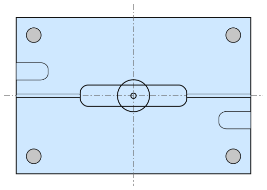
Top view 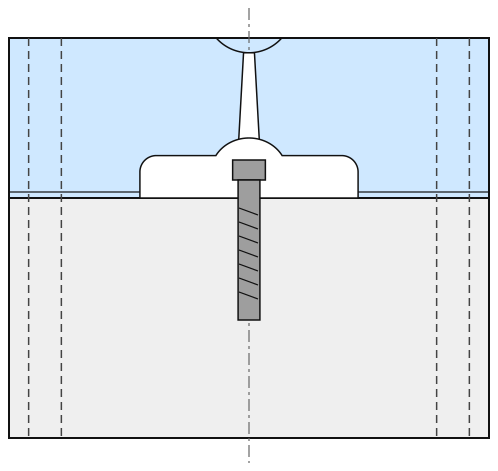
Front view 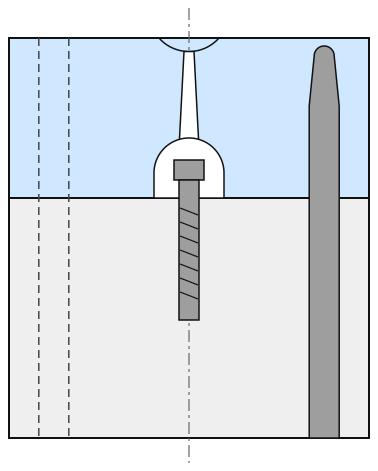
Right-side view We will return to these three standard-version drawings and add the section lines and related markings wherever they make the internal construction easier to understand.
-
3. Prepare and square the mold plates
Start with aluminum stock cut slightly oversize. Do not try to saw it to the finished dimensions. The milling machine will be used to establish flat, square reference surfaces and then bring the block to the dimensions shown on the drawing.
3A. Machine the first reference face
Place the block securely in the milling-machine vise with either the front or back face upward. Face-mill that surface until it is clean and flat. This becomes the first reference surface from which the other faces can be made square. Optional: If a clamping slot is part of the mold design and this is the most convenient setup for machining it, the slot may also be cut while this face is accessible.
3B. Machine the opposite face
Turn the block over and seat the newly machined face firmly against the vise or parallels. Face the opposite side until the two faces are parallel and the block is approaching the dimension shown on the drawing. Optional: A matching clamping slot may also be cut while this face is accessible.
3C. Square the remaining vertical sides
Rotate the block and machine the remaining side faces one at a time, always locating from surfaces that have already been machined. Measure as the work progresses and take lighter finishing cuts as the final dimensions are approached. For this project, try to make the finished dimensions agree with the drawing to within about 0.001 inch where practical.
The important lesson is not simply reaching a number on the caliper. The faces should also be flat, opposite faces should be parallel, and adjacent faces should be square to one another. A small dimensional error can often be tolerated more easily than a block that is tapered or out of square.
3D. Face the top and bottom
Once four sides have been established, the vise may no longer be the best way to hold the work. Use the milling-machine clamp kit to secure the block to the table and face the remaining top and bottom surfaces. Support the work on clean, equal-height surfaces so the already-machined sides remain square to the table. Thin paper can be used as a protective or friction layer where appropriate, but the machined reference surfaces—not compressible padding—should establish the alignment.
Again, measure frequently and approach the planned height with light final cuts. Allow the aluminum to cool before making a critical final measurement if machining has made it noticeably warm. The two mating mold faces should ultimately close flat against one another without rocking.
3E. Remove sharp edges
After all six faces have been brought to size, use a fine file or deburring tool to place a very small bevel on exposed sharp edges. The object is only to remove the knife-like corner so the mold is safer to handle; do not round over reference edges or the mold's mating surfaces.
3F. Finish the surfaces
Optional cosmetic finish: The outside faces may be sanded and polished if a cleaner appearance is desired, and a mirror finish can make a student project especially satisfying. On the mating or parting surfaces, however, preserving flatness and sharp reference edges is more important than making the surface shiny. Avoid aggressive hand polishing that could round an edge or change a carefully machined dimension.3G. Record the dimensions as actually machined
After the block has been finished and has returned to room temperature, measure its actual length, width, and height. If any finished dimension varies from the planned dimension, record the as-measured value on the working drawing. Do the same for any clamping slots or other reference features that have already been machined.
A small difference from the original plan does not necessarily ruin the mold. What is important is knowing exactly what was produced. Later holes, guide pins, the cavity, sprue, and other features can then be located accurately from the surfaces and dimensions that actually exist rather than from dimensions the block was intended to have. The working drawing should become an as-built record as the mold is made.
-
4. Lay out the mold and establish machine coordinates
Before drilling guide-pin holes or machining the cavity, establish visible layout marks on the mold blocks and then establish accurate X and Y reference coordinates on the milling machine. The scribed layout is primarily a visual check; the milling machine dials or a digital readout should be used for accurate positioning.
4A. Apply layout fluid
Lightly spray or brush layout fluid onto the areas of the mold where holes, the cavity, sprue, and other features will be machined. Allow it to dry before scribing. The dark coating makes fine scribed lines much easier to see against the aluminum.
A scribed line is not an accurate measuring surface. Depending on the point of the scriber and how heavily it is used, the visible line may be several thousandths of an inch wide and can easily approach about 0.010 inch. Treat the layout lines as a visual guide and a way to catch obvious mistakes, not as the final means of locating a drilled or milled feature.
4B. Scribe the important reference lines
Using a machinist's square, calipers, rule, and a sharp scriber, lightly mark the mold centerlines and the planned locations of the guide pins, cavity edges, sprue, insert, mounting holes, and other important features. Work from the actual dimensions recorded in Step 3G if the finished mold block differs slightly from the original drawing.
Keep the marks light. Their purpose is to let you look at the block and confirm that the planned features make sense before metal is removed. If a dimension is critical, locate it from a machined reference surface with the milling machine rather than trying to split a scribed line by eye.
4C. Clamp and support the mold blocks
Place and clamp the mold halves on the milling-machine table, making sure they are square with each other and with the machine's table travel. If a planned operation will drill completely through the mold, raise the blocks on parallels or place them on a flat piece of sacrificial stock so the drill cannot strike the machine table. Any supporting stock used for alignment should have flat, parallel faces and should be clean and free of chips.
4D. Find an edge with a known-diameter rod
A simple traditional method can be used when a commercial edge finder is not available. Place a straight rod of known diameter in the milling-machine collet; a 1/2-inch rod is convenient for this example. Bring the rod slowly toward one side of the mold block. Place a thin piece of paper between the rod and the block as a feeler. Very thin rolling paper is often close to 0.001 inch, but measure or verify the paper if an exact thickness is important.
Approach the block slowly until the paper is just gripped: it should not be loose, but it should still be possible to move it with a light pull. Do not force the rod into the block. This establishes the rod approximately one paper thickness away from the mold surface.
4E. Always approach from one direction
The table screws and nuts have some backlash. If the crank is reversed, the dial may turn before the table actually begins moving in the new direction. For this reason, make the final approach to the mold from the same direction each time. If you overshoot, back away farther than the backlash and then approach again from the original direction.
4F. Set the machine dial to a known edge
When the paper fit is correct, remove the paper and raise the rod so it clears the block. Move the table inward by one-half the rod diameter plus the paper thickness. With a 1/2-inch rod and 0.001-inch paper, that movement is 0.251 inch. The spindle centerline is now approximately over the edge of the mold block. Set that axis dial to zero.
Repeat the same procedure for the other table axis. It can also be repeated from the opposite ends or sides of the block as a check, remembering that each final approach must be made in the proper direction for that axis.
Layout marks show you where you expect to be; machine coordinates tell you where you actually are. Once the X and Y references have been established, use the milling-machine dials or digital readout to locate the guide-pin holes and other features from the drawing.With the mold blocks squared, clamped, visibly laid out, and the machine coordinates established, the next step is to drill and fit the guide-pin system that will make the two mold halves return to the same position every time they close.
-
5. Drill the alignment-pin and other holes
With the machine coordinates established, keep the two mold halves accurately aligned and clamp them securely together. Drilling the alignment-pin holes through both mold halves in the same setup is generally more accurate than locating and drilling the two halves separately, because each pin and its matching hole are established on the same centerline.
5A. Drill, ream, and lightly chamfer the four alignment-pin holes
Move the milling-machine table to the first guide-pin location using the coordinates established from the drawing. Spot the location if needed, then drill through both mold halves. Repeat the operation for all four guide-pin positions without disturbing the relationship between the two blocks.
If suitable reamers are available, drill each hole slightly undersize and then use the reamer to bring it accurately to the required size for the 3/8-inch alignment pins. Reaming improves the size and finish of the holes and helps the guide pins fit consistently.
Before removing the mold from this setup, lightly break the sharp edges of the pin holes. One convenient way is to substitute a larger drill and use only its point to make a very small chamfer. The object is to remove the burr, not to enlarge the working portion of the hole or create a deep countersink.
When cutting aluminum, use an appropriate cutting fluid and withdraw or jog the drill upward as needed so chips can clear from the flutes instead of packing in the hole. Kerosene has traditionally been used as a cutting fluid for aluminum, but because it is flammable it should be used only where the shop's safety rules permit it and ignition sources are controlled. A modern cutting fluid intended for aluminum is a suitable alternative.
5B. Drill the sprue opening, form the nozzle seat, and taper the sprue
Assuming the mold is oriented right-side up, the sprue can also be established during this setup. Drill through the upper mold half with a drill matching the nozzle opening called for by the molding machine, continuing only slightly into the lower mold half. This marks and centers the mating location without creating an unnecessary deep hole in the lower block.
Follow the drilled opening from the outside of the upper mold half with a ball-end mill whose radius matches the radius of the press nozzle. This forms the nozzle seat so the machine nozzle can bear against the mold properly at the sprue entrance.
The straight drilled sprue should then be given a slight taper. For this mold the sprue must remain smallest at the machine-nozzle side and become larger toward the cavity and molded part. When the mold opens, the solidified sprue can then pull freely out of the upper mold half with the molded handle rather than being locked into a reverse taper.
A simple taper reamer, such as a 1/8-inch to 5/8-inch handyman's reamer, is suitable for this introductory mold. Because the reamer becomes larger toward its handle, it must be worked from the inside/cavity side of the upper mold half toward the nozzle side. The larger portion of the reamer therefore enlarges the cavity end of the sprue while the nozzle end remains at approximately the original drilled diameter.
Hand reaming is recommended for a first mold. Work slowly, make small advances, and clear the chips often. A taper reamer can grab suddenly, especially in aluminum, and hand work gives much better feel for how aggressively it is cutting.
Optional powered method: It is possible to perform this operation in the milling machine, but the upper mold half must first be turned over so its cavity side faces upward and the existing sprue hole must be centered accurately under the spindle. One practical method is to place the same drill used to make the original sprue hole—or another close-fitting straight rod—in the collet, lower it gently into the drilled hole to locate the mold, and then clamp the mold securely. After the locating tool is raised and replaced with the taper reamer, use a very low speed and a series of short pecking or jogging cuts, withdrawing frequently to clear chips.Powered reaming should be treated cautiously. If the reamer grabs, it can stop the spindle, damage the mold, or break the tool. Unless there is a strong reason to power the operation, the slower hand method is the safer and more controllable choice for this project.
5C. Option: Prepare for the upper-platen shoulder bolts
For a mold that will remain mounted in the machine, leave the four upper-platen attachment holes undrilled until the mold can be located in the actual Morgan press. Morgan's setup procedure uses a 3/8-inch transfer punch through the upper-platen holes to mark the upper mold half. Remove the mold, drill and tap those four marked locations, and then install the shoulder bolts. The usual arrangement is a 3/8-inch shoulder bolt with a 5/16-18 threaded end. This transfer-punch method avoids depending on assumed hole coordinates.
5D. Option: Retain the alignment pins with set screws
If the finished alignment pins are to be positively retained in one mold half, this is a convenient time to drill and tap small holes from the outside edge of that block into the alignment-pin holes. A set screw can later bear against each pin. The pin may also be given a small flat or shallow notch where the set screw contacts it so the screw does not have to bite into a round polished surface.
This prevents loose guide pins from falling out whenever the mold is handled or turned over. Keep these retaining holes clear of the cavity, vents, mounting features, and other critical areas.
5E. Separate the mold halves and drill the insert recess
After the through-drilling operations are complete, remove the clamps and separate the mold halves. Clean the milling-machine table and all reference surfaces carefully; even a small aluminum chip or dust particle trapped beneath the mold can tilt the work and spoil an otherwise accurate setup.
Set up the appropriate mold half again from the established reference surfaces and drill or machine the hole into which the captured bolt, screw, or other insert will recess. Locate this feature from the actual machine coordinates and the as-built dimensions recorded earlier rather than relying on the scribed line alone.
Preserve the setup whenever it helps accuracy. Features that must line up between the two mold halves are best established while the halves are clamped together. Features that belong to only one half can be machined after the pair has been separated.With the guide-pin holes, sprue location, and insert recess established, the next major operation is machining the one-sided part cavity.
-
6. Machine the one-sided cavity
The cavity for this first T-handle is machined into the upper mold half only. Set that mold half on the milling machine with its parting face upward, which means the upper half is effectively upside down from its normal position in the molding machine. Clamp it securely, square it to the machine travel, and re-establish the X and Y references before beginning the cavity.
6A. Select the cutter and begin at the center
Select an end mill suitable for aluminum and for the shape shown on the drawing. Begin near the center of the planned cavity and remove only a small amount of material at a time. For the T-handle, a practical method is to mill across the cavity, move outward slightly, and then mill back across. Continue working outward in a controlled elongated rectangular pattern rather than trying to remove the entire cavity in one heavy cut.
The first few passes are a good opportunity to compare the cut with the scribed layout. The scribed lines are still only a visual check; the machine coordinates and measurements determine the actual finished location and size.
6B. Understand conventional and climb milling
Even on the first pass you may notice that one side of a cut looks cleaner than the other. This happens because the relationship between cutter rotation and table travel changes the way the cutting edge enters the aluminum. When the cutter action at the cut is in the same general direction as the feed, the operation is called climb milling, or down milling. When the cutter action opposes the feed, it is called conventional milling, or up milling.
A slot cut down the middle naturally has one side experiencing climb cutting and the other side conventional cutting. Once the cavity is opened up and individual walls are being finished, the direction of travel can be chosen deliberately.
6C. Use conventional milling for roughing when appropriate
Conventional milling is often the more forgiving choice for removing the bulk of the material on a manual milling machine that has noticeable backlash. It does not tend to pull the table into the cutter as aggressively as climb milling can. The tradeoff is that it usually creates more rubbing and friction at the beginning of the cut, and aluminum chips may smear or cling to the freshly cut wall if the cutter is dull or chip clearing is poor.
Keep the cutter sharp, use suitable cutting fluid, and clear chips frequently. Do not allow recut chips to collect between the cutter and the finished wall.
6D. Use climb milling carefully for the best finish
Climb milling generally produces the cleaner finished surface in aluminum, which makes it especially useful as the cavity approaches its final dimensions. However, the cutter also tends to pull the work and table in the direction of travel. On a manual mill with backlash, that pull can cause the table to jump farther than intended.
Backlash must therefore be controlled. Keep the final feed approach consistent, lock the axis that is not being moved, and if the machine permits it, a small amount of drag may be applied to the moving axis with its table lock or gib adjustment. Do not fully lock an axis that you are trying to feed. If the machine has excessive backlash or cannot be controlled smoothly, use conventional milling for roughing and reserve climb milling for very light finishing cuts.
6E. Work outward and downward a little at a time
For the T-handle cavity, be patient. Make a complete controlled pass, step outward slightly, and repeat until the planned outline is approached. Then lower the cutter a small amount (or raise the table, depending on the machine) and repeat the pattern at the next depth. Continue in shallow stages until the cavity approaches the depth shown on the drawing.
Avoid taking an unnecessarily deep cut merely to save time. Small, even cuts are easier to control, easier on the cutter, and make it much less likely that one mistake will spoil the mold.
6F. Measure repeatedly as the final dimensions approach
This is one of the habits that separates careful moldmaking from ordinary material removal: stop and measure often. As the cavity approaches its final width, length, and depth, make smaller and smaller corrections. A final dimensional cut may remove only about 0.001 inch where the machine, cutter, and measuring method make that practical.
After the final measured cut, repeat the same finishing path once more without changing the table or depth setting. This is commonly called a spring pass. The cutter and the work deflect slightly while under load; repeating the pass at the same setting allows the cutter to remove small high spots left as that elastic deflection relaxes.
Patience is part of moldmaking. Material removed from the cavity cannot be put back. The closer you get to the finished dimensions, the smaller the cut should become and the more often the cavity should be measured.6G. Add draft and the desired bottom radius
A cavity cut with an ordinary straight end mill will have nearly vertical walls. Those walls can grip the molded part and make hand removal unnecessarily difficult. A slight draft can be produced with a suitable tapered end mill, provided the taper agrees with the mold drawing.
The desired radius at the bottom of the cavity should also be planned rather than left to chance. One practical approach is to use a standard flat-bottom end mill for most of the rough cavity work, then change to a ball-end or corner-radius cutter for the final radiused surfaces specified on the drawing. This avoids making every roughing pass with the finishing cutter and gives better control over the final shape.
6H. Make the final finishing passes smoothly
Use a sharp cutter and try to keep the hand-feed rate as even as possible. Changes in feed pressure can show up in the mold surface, and whatever is left in the cavity surface may be reproduced on every molded part. Make the final finishing passes deliberately, clear the chips, inspect the walls and floor under good light, and measure the cavity one more time before removing the mold from the machine.
Once the cavity dimensions, draft, radii, and finish agree with the drawing, the next step is to fit the captured bolt or other metal insert and verify how it will be held during molding.
-
7. Capture the bolt in the molded handle
In this first T-handle, the bolt is not a temporary mold insert that will be removed later. The bolt becomes a permanent part of the finished molded handle. The recess machined for the bolt head must therefore be deep enough and shaped so that the head is completely captured by the plastic. There should be enough plastic around and over the head that normal pulling on the bolt cannot tear it out of the handle.
A hex-head bolt is especially useful because the flats of the head give the plastic a positive shape to mold around and help keep the bolt from turning inside the finished handle. Other head styles or purposely shaped metal inserts can also work, but the same idea applies: the metal should have enough mechanical engagement with the plastic that it cannot simply pull out or spin.
7A. Fit the bolt before molding
Test-fit the actual bolt that will be molded into the handle. Its head should sit at the planned depth and location without rocking, and the threaded shank should project from the mold by the amount shown on the drawing. The bolt must also remain securely located while the mold closes and while plastic is injected around the head.
Optional method: the hole that receives the threaded shank may itself be tapped. The bolt can then be screwed into the mold to the desired depth before each shot. This makes it possible to use otherwise identical handles with different exposed bolt lengths. After molding and opening the mold, the finished handle and its permanently captured bolt are simply unscrewed from the mold. This tapped hole is only a way of holding the metal bolt during molding; it is not a method of molding the plastic thread discussed below.
7B. A warning about molded-in threads: the tolerances work backwards
It is tempting to think that a normal nut and bolt can simply be used as matching mold forms. For example, a beginner might tap a hole in the mold and think, “I can just unscrew the molded knob afterward and I will have a one-piece threaded plastic part.” A threaded part can certainly be molded and unscrewed from its tooling, but the thread dimensions must be designed for molding. A standard matching nut and bolt do not automatically make matching molded plastic threads.
Ignore the thread shape for a moment and consider a simple round rod and hole. Suppose the finished parts are intended to fit loosely together, with a 0.990-inch male rod fitting into a 1.010-inch female hole. The mold feature that creates the female hole must therefore be about 1.010 inches in diameter, while the mold opening that creates the male rod must be about 0.990 inch. In other words, the mold rod is larger than the mold hole. The clearance relationship in the tooling is the reverse of the clearance relationship in the finished parts.
Threads behave the same way, except that their geometry is more complicated. A metal bolt used as a core forms a female plastic thread; a metal nut or threaded cavity forms a male plastic thread. The normal clearance built into a matching metal nut and bolt is therefore being used in the opposite role when those pieces become mold tooling. On top of that, the plastic shrinks as it cools. If an ordinary nut and bolt are used blindly as the two matching mold forms, the two molded plastic threaded parts should not be expected to fit one another correctly.
Design the molded thread, not just the metal tool. Allow for the shrinkage of the actual resin and for the clearance required in the finished mating parts. The fact that a metal nut fits a metal bolt does not mean that plastic parts molded from those two shapes will fit each other. -
8. Add the vents
This simple T-handle mold may appear to work without deliberate vents, especially if very fine tooling marks remain on the parting surfaces. Those tiny surface irregularities can sometimes give trapped air a path out. Even so, a useful moldmaking rule is: “A mold isn’t finished without vents.” It is better to provide the air with a planned escape path than to depend on accidental surface marks.
8A. Check the resin information first
Vent dimensions are affected by the plastic being molded. Before treating any vent size as universal, check the technical or processing data for the exact resin grade being used. A vent that is suitable for one material may be too deep or too shallow for another. For this introductory mold, we will use the dimensions below as a practical starting point.
8B. Cut the vents in the upper mold half
Use a 3/32-inch end mill and cut the vent channels approximately 0.010 inch deep. Begin at the cavity and mill outward to the outside edges of the mold. For the T-handle, place the vents so they lead away from the ends of the handle cavity, giving the air at those last-to-fill areas a direct route out of the mold.
These vents also help the molten plastic fill all the way to the ends of the handle. Instead of forcing trapped air to find random paths along the parting line, the vents give it a deliberate escape route. That can reduce trapped-air problems and reduce the tendency to develop a thin flash around the molded part as pressure builds while the cavity fills.
8C. Keep the vents out of the lower mold half
On this particular one-sided mold, cut the vents into the upper mold half only. The lower half forms the flat face of the finished handle. Even a very shallow groove placed there can reproduce itself in the molded plastic as a ridge or thin projection. Keeping the vent cuts in the upper half avoids intentionally adding such marks to that finished surface.
8D. Add two mold-opening pry slots
A hand-placed mold still has to be opened after it is removed from the press. A thin knife blade at the parting line can sometimes start the separation, but it is much better to give the operator two intentional places for a screwdriver or similar flat tool to enter. Machine a small pry slot at each end of the mold so the halves can be opened gradually and evenly instead of being forced apart from only one side.
The exact slot dimensions can be left to the mold maker and the tools available. They only need to admit the intended prying tool without weakening the mold. Locate the two slots so they do not cut into the cavity, alignment-pin area, or vent channels. If necessary, offset the slots in opposite directions so each has a clear path around the vents.
Give the air somewhere to go—and give yourself somewhere to open the mold. Deliberate vents control the escaping air, while deliberate pry slots make the closed mold much easier to separate without damaging the parting surfaces. -
9. Make the alignment pins and complete the mechanical fit
With the remaining mold machining complete, make and fit the four alignment pins. The pins must be straight, smooth, and consistent enough to guide the mold halves together without binding, yet they should not be so loose that they simply fall out whenever the mold is handled.
9A. Turn and finish the alignment pins
The pins can be made from suitable round stock on the lathe. Nominal rod stock may be a little too tight for a drilled and reamed hole, so bring each pin to its final fit gradually. Fine abrasive paper can be used while the pin turns in the lathe to polish it evenly, then the pin can be cut to the required length and its ends lightly chamfered.
It is generally better to fit the pins to the reamed holes than to aggressively sand the holes themselves. If a hole only has a small burr or rough edge, correct that locally. Heavy sanding inside a reamed hole can make it tapered or bell-mouthed and destroy the accuracy gained by reaming.
9B. Decide which mold half will retain the pins
The pins should remain with one mold half when the mold is opened. A close fit may be enough to retain them. Optional: the set screws described in Step 5 provide a more positive method. If set screws are used, align the screw with the small flat or notch prepared on the pin and tighten it only enough to retain the pin securely.
The mating mold half must slide over the exposed portions of the pins smoothly. If the mold has to be hammered together or forced apart, the fit is too tight or something is out of alignment. Correct the cause rather than forcing the mold.
9C. Check the parting surfaces and the opening slots
Clean both mating faces thoroughly and close the mold by hand. The faces should meet flat, with no visible gap and no rocking. A single chip, raised burr, or small ding can hold the mold open enough to create flash during molding.
Then open the mold using the two pry slots made earlier. Work from one end to the other in small amounts so the mold opens evenly on the guide pins. The slots should make a knife blade unnecessary and should allow the mold to be separated without damaging the precision parting surfaces.
9D. Deburr the remaining machined features
Remove remaining burrs from drilled holes, vent exits, pry slots, and other machined features. Break exposed sharp outside edges lightly for safe handling, but do not round the cavity edge, parting line, or other surfaces that must remain sharp and accurate. Leave the detailed cavity sanding and polishing for the next step.
Important exception — do not bevel the nozzle-side edge of the sprue hole. The Morgan nozzle seats firmly in the ball-milled recess above the sprue, and the nozzle's central opening feeds directly into the smallest end of the tapered sprue. Those two openings should be the same diameter, or the opening in the mold may be only slightly larger. Keep that edge clean, concentric, and essentially sharp rather than chamfering or countersinking it. A bevel there can fill with plastic and form a thin ring or flange above the sprue. That ring can catch on the mold and prevent the cooled sprue from being pulled downward through the upper mold half when the mold opens.Finally, insert the actual bolt to be molded into the handle and close the mold once more. Confirm that the bolt is held at the correct depth, the guide pins enter smoothly, the mold closes completely, and the mold can be opened again using the pry slots. At this point the mold should operate mechanically as a complete assembly before final cavity finishing begins.
-
10. Finish and polish the cavity
The cavity is not finished merely because its dimensions are correct. Rotating cutters leave extremely fine circular or helical tool marks. On the side walls of a cavity, those marks can run across the direction in which the molded part must be removed. Plastic can grip those tiny scratches surprisingly well, especially when the walls have little draft. Ball-end mills also leave visible machining marks on the floor and radiused portions of the cavity.
Removing these marks is part of mold fitting and polishing. In many mold shops, much of the machining may be done by general machinists, while the final fitting, stoning, sanding, and polishing are performed by mold makers because the last handwork directly affects both release and the appearance of every molded part.
10A. Sand in the direction the part will leave the mold
Work from a coarser abrasive toward progressively finer grades, just as with ordinary sanding. On the side walls, however, the direction of the sanding strokes matters. For this T-handle the part is pulled straight out of the cavity, so the side walls should be sanded with strokes that run up and down in the direction of part removal. Do not sand sideways across those walls.
Sideways scratches can act like microscopic barbs across the withdrawal path. Just as important, do not change the geometry while polishing. Be especially careful not to create an undercut or an outward taper toward the bottom of the cavity. Preserve whatever draft was deliberately machined into the walls.
10B. Make simple sanding tools for the cavity
Fingers are often too large to reach the bottom and sides evenly. Small sanding sticks can be made from scraps of wood shaped to fit the cavity, with abrasive paper glued or wrapped around them. Other backing forms can be made from material that can be shaped to the cavity, such as damp cardboard allowed to dry in the desired form. The backing should support the abrasive so pressure is applied evenly rather than only at one fingertip.
For the cavity side walls, avoid rotary sanding or polishing tools. A rotary tool tends to put scratches back across the direction of release and makes it easy to round edges or locally alter the draft. Hand work is slower, but it gives much better control. Expect the final cavity finish to take time; several patient hours in an evening is entirely reasonable for a first mold.
10C. Progress from tool marks to polishing
Begin with an abrasive only coarse enough to remove the remaining cutter marks, then move through finer grades until the sanding scratches from the previous grade are gone. Continue to polishing compound or very fine polishing media if a glossy molded surface is desired. Do not jump directly from obvious milling marks to a fine polishing compound; the fine polish will make the existing scratches shinier rather than remove them.
The floor and radiused portions of the cavity should also be worked progressively to remove the marks left by the end mills. Whatever texture remains in the mold can be reproduced on every molded handle, so inspect the cavity under good light as the finish improves.
10D. Protect the sharp parting edge
Be particularly careful where the cavity meets the flat parting surface. That edge should remain sharp and well defined. Rounding it during sanding or polishing creates a small unwanted gap when the mold is closed and can encourage flash around the finished part. The parting surface itself should remain flat.
The sprue can also be polished, but use strokes along its length, in the same direction the cooled sprue will be withdrawn. Do not roll the abrasive around the sprue in a way that leaves strong circumferential scratches. Preserve the taper and avoid enlarging the small nozzle end.
10E. Option: Lettering, engraving, or a matte finish
If lettering, numbers, a logo, or other identification are to appear on the molded part, this is a logical stage to have the mold professionally engraved. Mold engraving is a specialty, and a beginner may prefer to take the finished mold half to someone equipped for the work. Avoid the temptation to create cavity lettering with ordinary metal stamps: stamping displaces metal rather than removing it and can distort the surrounding cavity surface.
A cavity with adequate draft can also be lightly abrasive-blasted to create a uniform matte molded finish. Masking can be used to combine polished and matte areas on the same part. Even when a matte finish is desired, remove and polish out the machining marks first; otherwise the original cutter pattern can remain visible through the blasted texture.
10F. Option: Polish the exterior of the mold
The outside of the mold may also be sanded and polished if a clean presentation is desired, but this is cosmetic rather than necessary to make the mold function. Spend the time first on the cavity, sprue, mating surfaces, and other areas that directly affect molding and release.
The finish direction is part of the mold design. On surfaces that slide past the molded part during ejection, scratches should run with the direction of movement, not across it. Polish carefully enough to remove tool marks without changing the dimensions, draft, or sharp parting edge. -
11. Make the first supervised molding trial
With the mold mechanically complete, the next job is to learn what happens when hot plastic is actually pushed through it. This first molding work should be done with an experienced operator or instructor. Verify the machine setup, mold position, nozzle seating, clearances, and the resin manufacturer's processing information before making the first shot.
11A. Dry and prepare the plastic
Before heating the machine, decide whether the resin needs to be dried. Pellets exposed to shop air can absorb moisture, and moisture can show up as streaks, bubbles, splay, inconsistent flow, or poor mechanical properties. A freshly opened, properly sealed bag may sometimes be usable as supplied, depending on the resin, but the exact grade's technical data sheet should control the decision.
Material can be batch dried in shallow trays in a suitable temperature-controlled drying oven or continuously in a hopper dryer intended for plastics. A hopper dryer has the additional advantage of delivering warm material to the machine, which can reduce the time and energy required to bring the pellets to molding temperature and can make recovery between shots more consistent.
11B. Temperature is only part of the story
Plastic heats slowly into a useful molding range, but once it is hot, time at temperature matters just as much as the temperature itself. If a thermoplastic remains hot too long, its polymer chains can begin to break down. A degraded or “burnt” part may still fill the mold and may even look acceptable, yet have much less mechanical strength than expected.
Watch the molded parts continuously for changes in color, odor, brittleness, strength, or surface appearance. If degraded material is suspected, stop and purge the machine as appropriate for the resin and the machine rather than continuing to mold questionable parts. Where strength matters, periodically test sample parts instead of judging quality only by appearance.
11C. Flow depends on temperature, time, speed, pressure, and mold temperature
The melt does not respond to only one control. Barrel and nozzle temperature, residence time, injection pressure, injection speed, and the temperature of the mold all affect how easily the plastic flows. Many thermoplastics are shear-thinning, meaning that increasing the injection speed can lower the material's apparent viscosity while it is flowing. Faster injection can also add some shear heating. This is useful, but it is not the same thing as allowing the material to sit hot until it degrades.
The aluminum mold also warms during the first several shots. As it warms, the plastic may flow farther and fill thin or distant areas more readily. This is one reason the settings that produced the first shot may not produce exactly the same result several shots later.
11D. Keep mold-opening force below the available clamp force
Pressure inside the cavity acts over the projected area of the molded part and tries to force the two mold halves apart. A useful first approximation is:
Projected area × cavity pressure = mold-opening force
If area is in square inches and pressure is in PSI, the result is pounds of force. Divide by 2,000 for tons.The projected area is the silhouette of the part as viewed in the direction the mold opens, including the pressurized projected area of the sprue and runners where applicable. Actual cavity pressure is normally lower than the machine's injection pressure because pressure is lost through the nozzle, sprue, runner, and gate. For a conservative beginner check, the machine injection pressure can be used as an upper-bound estimate. The calculated opening force should remain below the available mold clamping force.
If cavity force overcomes the clamp, the mold can separate slightly and form flash around the parting line. A separate sealing problem can occur between the machine nozzle and the ball-milled nozzle seat, producing flash or leakage there if the fit, alignment, or nozzle contact force is inadequate.
11E. Establish a repeatable cycle
Because both the resin and the mold are affected by time and temperature, try to establish a consistent interval between shots. This matters even when the mold is being placed and removed by hand. If one shot follows quickly and the next sits for several minutes, the resin residence time and mold temperature have changed, making the results difficult to compare.
11F. Expect the first few shots to be setup pieces
The first shot is unlikely to be the first usable part. It may be a short shot, may flash, or may simply look different because the mold is still cold. The first few shots may also pick up small traces of aluminum, polishing compound, or other residue left from the finishing operations. Inspect the mold and clean it before use, but still expect the first shots to serve mainly as setup pieces.
Make small adjustments and allow the machine, mold, material, and cycle time to approach a repeatable condition. After several shots, the operator may begin producing parts that are complete and consistent. At that point, evaluate the actual molded part for fill, flash, release, dimensions, surface finish, and strength. Then decide whether the run should continue or whether the mold should return to the bench for polishing, vent changes, additional machining, or another correction.
11G. Keep a molding log for every mold and part
Start a permanent log for the part and add a new entry whenever a setting or condition changes. At a minimum, record the date and time, exact resin and grade, material preparation or drying condition, cycle time, barrel temperature, nozzle temperature, injection pressure, injection speed, number of parts molded, comments, and the operator's initials. Room temperature and relative humidity are useful additions; atmospheric pressure may also be recorded if the shop wants a more complete environmental history.
If mold temperature is measured, record that as well. The log should become the proven setup history for that mold. Keep these records together in a notebook or other permanent system so a future operator can reproduce a successful run rather than beginning from guesswork each time.
Optional computer aid: A simple computer program can maintain the mold log and also act as an adjustable cycle timer, sounding a tone when it is time to make the next shot. This can be especially useful with a hand-placed mold because it removes one source of cycle-time variation.11H. Option: Leave the mold in the machine
Hand placement is perfectly reasonable for testing a new cavity, making a few prototypes, or producing a very small number of parts. If more parts are required, however, even a simple mounted mold that opens and closes with the press can greatly improve cycle time and repeatability. The lower half can be clamped to the lower platen and the upper half attached to the moving platen while the operator still removes the part manually.
Once the cycle is faster and more consistent, the processing settings can be optimized for that new operating rhythm. A setting that worked during slow hand placement may not be the best setting after the mold remains warm and resin residence time becomes shorter and more consistent.
11I. Match mold complexity to the number of parts required
There is always a balance between the cost of building the mold and the cost of producing each part. For a very short run it may be cheaper to drill a hole in each molded part afterward. For a long run it may be worth spending considerably more on the mold so that the hole, undercut, insert, or other feature is formed automatically during molding. The same tradeoff applies to hand-loaded inserts, loose cores, ejector systems, slides, automatic opening, and many other mold features.
The best mold is not necessarily the most complicated mold. It is the mold that makes the required part reliably, at the required quality and quantity, for a sensible total cost.
Improvements on This Mold Design
The first T-handle mold was intentionally kept simple so the builder could learn the complete process without adding mechanisms that were not necessary for a first successful part. Once the mold has been tested, however, several practical improvements can make it faster to operate, easier to maintain, and better suited to repeated production. None of the changes below are required for the first mold; they are examples of how a working prototype can evolve.
Deluxe mold: section and operating views
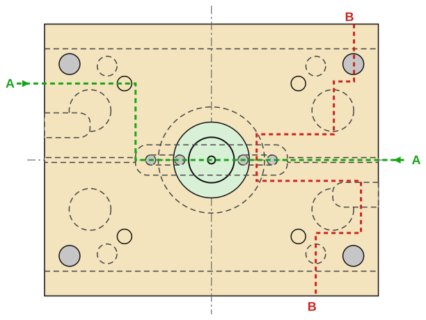
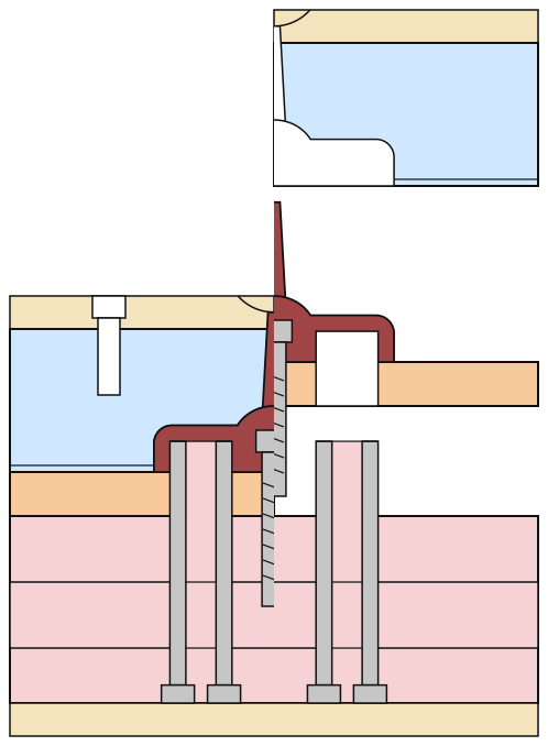
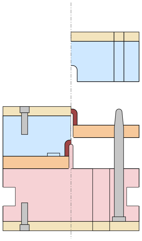
Option: Clamp and mount the mold permanently in the press
The most useful first improvement is the one mentioned earlier: stop removing and replacing the mold for every shot. Clamp the lower mold half securely to the lower platen and attach the upper half to the moving platen so the press opens and closes the mold automatically. This shortens the cycle, keeps the nozzle and sprue aligned from shot to shot, and makes mold temperature and resin residence time much more consistent.
The mold may still be operated with the part removed by hand. Full automatic ejection is not necessary to gain a large improvement in repeatability and cycle time.
Option: Make the molded handle stay with the lower mold half
With the simple arrangement used for this first mold, the molded handle naturally tends to remain in the upper cavity when the mold opens. This is only a minor inconvenience, but the operator must reach in and pull or pry the part downward while holding the molded-in bolt.
As discussed earlier, the bolt-receiving hole in the lower mold half can instead be threaded. The bolt is screwed into that hole before molding, so the finished handle remains attached to the lower half as the mold opens. The operator then removes the part by unscrewing the handle. The hole does not have to be threaded for its full depth. A short threaded section followed by clearance can hold the bolt securely while reducing the number of turns required to remove each finished part.
Option: Add steel guide bushings for the alignment pins
Repeated sliding of steel alignment pins directly in aluminum can eventually wear, score, or gall the aluminum holes. A steel cylindrical bushing can be fitted into each receiving hole so the pin runs against steel instead. The bushing can be made replaceable and, in a simple version, retained with a small set screw from the side in much the same way as an alignment pin.
This changes a wear-prone aluminum surface into a replaceable steel component and can extend the useful life of a mold that is opened and closed many times.
Option: Replace the nozzle seat and sprue entrance with a steel sprue bushing
The upper surface around the sprue receives repeated contact from the machine nozzle and is also exposed to hot, pressurized plastic. It is therefore one of the areas of an aluminum mold most likely to show wear. Instead of machining the semi-spherical nozzle seat and sprue directly into the aluminum forever, that feature can be made as a replaceable steel insert, commonly called a sprue bushing.
A simple sprue bushing can be inserted from the top and made with a shoulder so it rests positively in the upper mold half. The machine nozzle then presses against the steel seat rather than directly against the aluminum. If the seat or sprue eventually wears, the bushing can be replaced without remachining the entire mold half. The nozzle-side sprue edge must still remain sharp and properly matched to the nozzle opening so the molded sprue can pull downward through the mold when it opens.
Option: Capture the pins and steel inserts with retaining plates
Set screws are a convenient way to retain individual pins and bushings, but a more developed mold can use a plate on the top of the upper mold half and another plate on the bottom of the lower mold half. The rear ends of the alignment pins, guide bushings, sprue bushing, and other replaceable inserts can then be trapped mechanically between the mold body and these plates.
The retaining plates can be fastened with recessed socket-head cap screws so the screw heads remain below the outside surface. Any opening around the sprue bushing must leave the nozzle seat fully accessible. This arrangement makes the wear components serviceable while eliminating several side set screws and gives the mold a more conventional assembled construction.
Option: Core the underside of the part and use a stripper plate
An important improvement to this part would be to core its bottom side rather than molding the handle as a heavy solid mass. Coring reduces the wall thickness, which allows the part to cool more quickly, shortens the molding cycle, uses less material, and reduces the tendency for shrinkage, sink, and warping.
If keeping the option to unscrew the part is still desired, a stripper plate can be used. In that arrangement the stripper plate lifts the molded handle above the fixed cores during opening. The stripper plate may simply act as a lifting plate, or it may also contain the threaded receiver, depending on how the mold is designed.
Machining such a feature on a manual milling machine can be a demanding job. The fitting must be extremely accurate, because any clearance between the moving stripper plate and the fixed cores can allow plastic to flash between them. One workable method is outlined below.
One practical manual-machining method
-
Begin with a 3-inch-thick B-plate. In the present deluxe design, the finished lower mold body below the stripper plate is 2-1/8 inches thick, the stripper plate is 1/2 inch thick, and the integral cores project 3/8 inch above the stripper plate. The added material is therefore 7/8 inch total: 1/2 inch for the stripper plate plus 3/8 inch for the core projection. After machining, the lower mold body remains 2-1/8 inches thick while the two cores stand at the original top surface of the 3-inch B-plate.
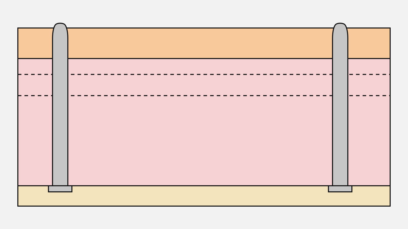
- Provide two cores, one for each side of the T-handle. Each core is 3/8 inch high above the stripper plate. Since the T-handle body is 1/2 inch thick, this leaves approximately 1/8 inch of plastic wall thickness over the cored area. The stripper plate must contain matching openings so the cores can pass through it with a very precise fit.
-
Begin by stacking and aligning the stripper plate on top of the lower mold half. With the two pieces clamped together, drill through at the ends of each future core opening, passing through the stripper plate and deeply into the lower mold half.
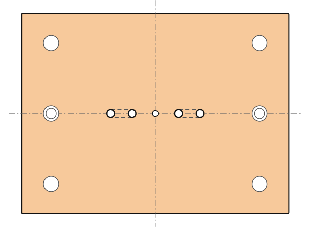
White circles mark the drill locations at the ends of the two future core openings. -
The drilled depth should exceed the core height and, ideally, continue all the way through the lower mold half. If that is not convenient at first, the holes can be completed later from the underside.
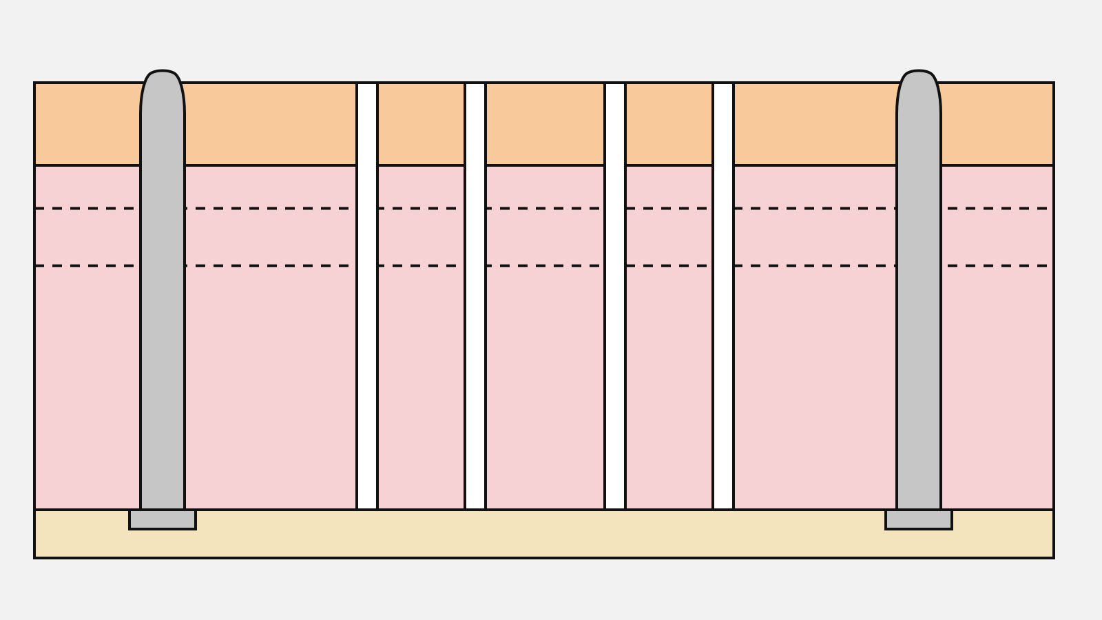
The four core-pin holes are drilled full depth to the bottom keeper plate. -
Remove the stripper plate and machine it separately. Mill a slot precisely between the drilled holes so each core can pass through the plate cleanly and accurately.
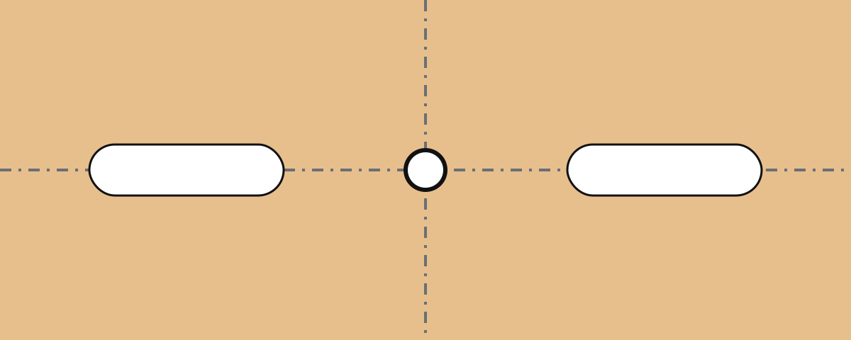
The stripper plate is milled between each drilled pair to form the close-fitting core openings. - Set up the lower mold half and finish drilling from the underside if needed. These relief holes may be slightly larger in the lower region, but that larger diameter must not continue upward into the close-fitting core area near the stripper plate.
-
With the lower mold half right side up again, rough out the surrounding area and leave the future cores standing proud. For this design, machine the surrounding area down 7/8 inch: 1/2 inch for the stripper plate plus 3/8 inch for the finished core projection. Mark the boundaries carefully and leave a small margin around the cores for final precision machining.
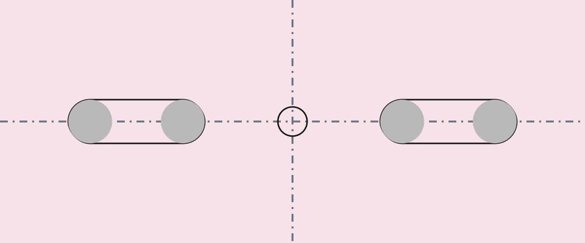
Top view while machining away the surrounding B-plate material and leaving the core areas standing. - Next, machine the ends of the future core very accurately so they relate properly to the drilled pin locations. Then remove the work from the milling machine, install the pins, and set the work back up.
-
Finish milling the core to its final width so it matches the pins precisely. If desired, the last thousandth of an inch can be brought in by careful hand filing, stoning, or polishing rather than by risking contact with the pins during a final milling pass.
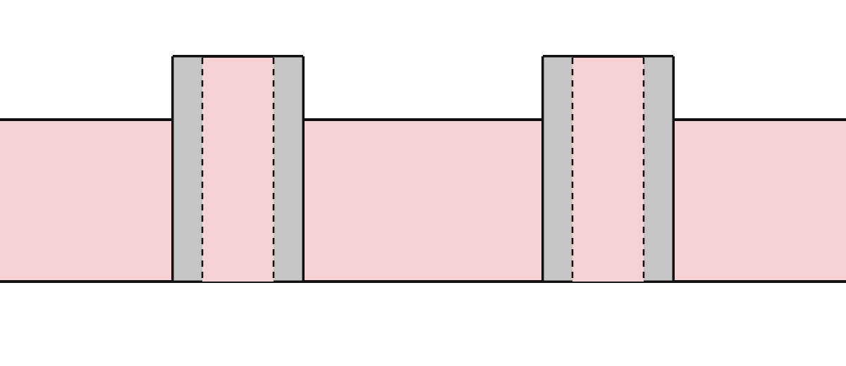
Front view showing the raised cores and the inserted pins during final precision machining. - Assemble the lower mold half with the pins installed and the finished core extending through the stripper plate. The fit must be as close to perfect as possible. If necessary, file, sand, stone, and polish both the core and the stripper-plate opening until they move freely but do not leave a gap where plastic can escape.
- Once the fit is correct, finish the exposed upper portions of the core and pins by hand. A slight taper, softened corners, rounded transitions, and a fine polish are all desirable so the molded part will release more easily.
This is the art and skill of mold making: creating parts that fit each other closely enough to control molten plastic, yet move smoothly enough to be practical in use.
Why we would not make the cavity removable on this first mold
A removable cavity insert is certainly possible, but it adds more complexity than this particular beginner mold needs. The cavity insert would have to locate accurately, seal properly against the surrounding mold and sprue system, and may require another retaining plate or supporting structure. If the cavity were made from steel, machining and hand polishing it would also be more demanding than performing the same work in the aluminum mold body.
For those reasons, the useful improvements above concentrate first on mounting, part removal, and replaceable wear components while leaving the actual T-handle cavity in the aluminum upper mold half. A removable cavity becomes more attractive later, when interchangeability or very long mold life is important enough to justify the added machining and fitting.
Where to Go Next
Once this mold can be machined, assembled, mounted, filled, opened, stripped, and operated reliably, the same skills can be extended to still more advanced moldmaking techniques. These may include ejector-pin systems, replaceable or loose inserts, threaded and removable cores, cam-operated slides, side actions, interchangeable cavity components, multiple-cavity molds, and more sophisticated gating and ejection systems.